


Views: 0 Author: Site Editor Publish Time: 2026-11-23 Origin: Site


The shift toward high-density interconnect (HDI) and flexible printed circuit boards (FPCs) requires copper foil thicknesses down to 9µm or less. Rolled copper foil outperforms electrodeposited (ED) copper in these applications due to its superior flexibility. This exposes the mechanical limits of standard rolling mill tooling. Inconsistent foil gauge, surface defects, accelerated oxidation, and poor substrate adhesion frequently stem from degraded or improperly specified work rolls. These tooling failures cause high scrap rates and rejected PCB batches.
To hit strict manufacturing tolerances like precise 1 oz or sub-oz copper weights, mill operators need specialized tooling. Precision rolling demands exact control over thermal camber, surface finish, and mechanical deflection. This guide details the technical specifications, metallurgical requirements, and supplier evaluation criteria needed to source high-performance PCB Copper Foil Rolling Rolls.
Material Superiority: The Cr3 Forged Steel Work Roll is the industry baseline for balancing extreme surface hardness with the deep structural toughness required for continuous copper foil reduction.
Surface Profile Dictates Yield and Purity: The work roll’s grinding and polishing tolerances directly dictate the foil's surface roughness (Ra/Rz), which is critical for subsequent lamination, signal integrity, and resistance to surface oxidation.
Thermal and Deflection Management: Precise crown profiling is non-negotiable to manage thermal camber and mechanical deflection during high-speed cold rolling, ensuring uniform gauge across varying coil widths.
Supplier Vetting: Evaluating a Cold Rolling Mill Roll Supplier's non-destructive testing (NDT) and heat treatment validation is as critical as the dimensional specifications of the roll itself.
Work roll deflection under high rolling forces directly causes gauge variations in the finished copper strip. When reducing copper to ultra-thin gauges, the separating forces push the rolls apart. This elastic deformation bends the roll barrel. If the roll lacks sufficient rigidity, the center of the copper strip becomes thicker than the edges, creating a convex profile. PCB manufacturing requires strict adherence to thickness standards. A standard 1 oz copper layer requires a consistent 1.37 mils thickness across the entire board. Deviations from this target compromise impedance control in multi-layer boards. Operators specify rolls with a high modulus of elasticity and exact crown profiles to counteract this flattening effect. In 20-high cluster mills, the work rolls rely heavily on the backing assemblies, but the primary work roll must still maintain absolute dimensional stability under load.
The extreme pressure exerted by the work roll fundamentally alters the copper's internal structure. Cold rolling elongates the equiaxed grain structure horizontally along the rolling direction. This roll-induced grain alignment is mandatory for flexible PCBs. Horizontal grains slide past each other during dynamic bending, providing exceptional fatigue resistance. Electrodeposited copper, with its vertical grain structure, easily cracks under similar stress. This dense, aligned grain structure also optimizes high-frequency current flow. Smooth, continuous grain boundaries reduce signal loss in high-speed digital circuits. The work roll applies uniform pressure to ensure this metallurgical transformation occurs evenly across the entire coil width. Any variation in roll pressure creates localized areas of incomplete grain elongation, leading to weak spots in the final flexible circuit.
The surface finish of the work roll transfers directly to the copper foil during the final reduction pass. Specific roughness profiles are required for the foil to bond effectively with insulating substrates like FR4 or polyimide. If the roll is too smooth, the foil lacks the mechanical tooth necessary for high peel strength. If the roll is too rough, the resulting peaks and valleys on the copper surface degrade signal integrity due to the skin effect at high frequencies. A poorly finished roll creates micro-crevices on the foil. These microscopic defects trap air and moisture, accelerating unwanted surface oxidation before the lamination process begins. Operators monitor the Ra (average roughness) and Rz (maximum peak-to-valley height) of the rolls daily to prevent these adhesion and oxidation failures.
Common foil defects trace back directly to specific work roll failures. Pinholes often result from non-metallic inclusions in the roll surface breaking loose and pressing into the thin copper strip. Edge cracking occurs when improper roll crown causes excessive reduction at the strip edges, exhausting the metal's ductility. Chatter marks appear as transverse lines across the foil. These marks indicate severe mill vibration, often caused by uneven roll wear, poor concentricity, or inadequate bearing fits. Identifying these defects on the inspection line triggers an immediate audit of the current roll inventory and grinding practices. Operators pull the offending roll from the mill and send it to the roll shop for complete profilometer mapping and regrinding.
Roll Defect Troubleshooting Matrix | ||
Observed Foil Defect | Probable Roll Condition | Corrective Action |
|---|---|---|
Continuous Pinholes | Surface spalling or micro-pitting on the roll face. | Remove roll, perform magnetic particle inspection, regrind past defect depth. |
Center Buckle (Wavy Center) | Excessive roll crown or severe thermal expansion in the roll center. | Increase coolant flow to center, reduce mechanical crown on next grind. |
Edge Wave | Insufficient roll crown or excessive roll bending under load. | Increase mechanical crown, check backup roll profiles. |
Transverse Chatter Marks | Out-of-round roll, bearing wear, or grinder vibration transfer. | Check Total Indicator Runout (TIR), true the grinding wheel, replace bearings. |
Herringbone Patterns | Uneven localized wear or improper coolant distribution. | Clean coolant headers, verify hardness uniformity across the roll barrel. |
The metallurgical composition of 3% Chromium (Cr3) forged steel makes it the premier choice for cold rolling non-ferrous metals. Chromium acts as a powerful carbide former. During heat treatment, these chromium carbides distribute evenly throughout the steel matrix. This provides exceptional wear resistance without the extreme brittleness associated with cast iron rolls. A Cr3 Forged Steel Work Roll maintains its surface finish longer than standard carbon steel alternatives. This extended surface retention is critical when rolling copper foil, as any degradation in the roll face immediately impacts the foil's surface quality and oxidation resistance. The forging process aligns the grain structure of the steel itself, eliminating the porosity and internal voids commonly found in cast alternatives.
Specifying a Copper Foil Cold Rolling Work Roll requires balancing surface hardness with core toughness. The roll surface must resist abrasive wear from the copper strip and withstand high contact stresses. Engineers typically specify a surface hardness of 90-95 Shore C for these finishing applications. A roll hardened entirely through its cross-section would shatter under the immense bending forces of the mill. The roll features a deep, uniform hardened outer layer transitioning smoothly into a tough, ductile core. This softer core absorbs shock loads, dampens vibration, and prevents catastrophic roll breakage during sudden mill stalls or strip cobbles. The depth of this hardened layer dictates how many times the roll can be reground before it reaches its scrap diameter.
Some specialized mills utilize high-speed steel (HSS) or semi-HSS rolls for ultra-thin foil finishing passes. HSS rolls offer superior hardness retention at elevated operating temperatures. They contain higher percentages of tungsten, molybdenum, and vanadium. This composition creates extremely hard complex carbides, extending campaign lengths between regrinds. HSS rolls are significantly more expensive and require highly specialized grinding wheels, such as cubic boron nitride (CBN), to redress. For the vast majority of PCB copper foil production, Cr3 forged steel provides the optimal cost-to-performance ratio. It delivers the necessary surface finish without the prohibitive maintenance costs and complex grinding requirements of HSS.
Material Comparison: Cr3 Forged Steel vs. High-Speed Steel (HSS) | ||
Specification | Cr3 Forged Steel | High-Speed Steel (HSS) |
|---|---|---|
Primary Alloying Elements | Chromium (approx. 3%), Carbon | Tungsten, Molybdenum, Vanadium |
Typical Surface Hardness | 90 - 95 Shore C | 92 - 98 Shore C |
Wear Resistance | Excellent for standard foil gauges | Superior, ideal for ultra-thin passes |
Grinding Requirements | Standard aluminum oxide wheels | Requires specialized CBN wheels |
Thermal Shock Resistance | High | Moderate to Low |
Initial Procurement Cost | Moderate | High |
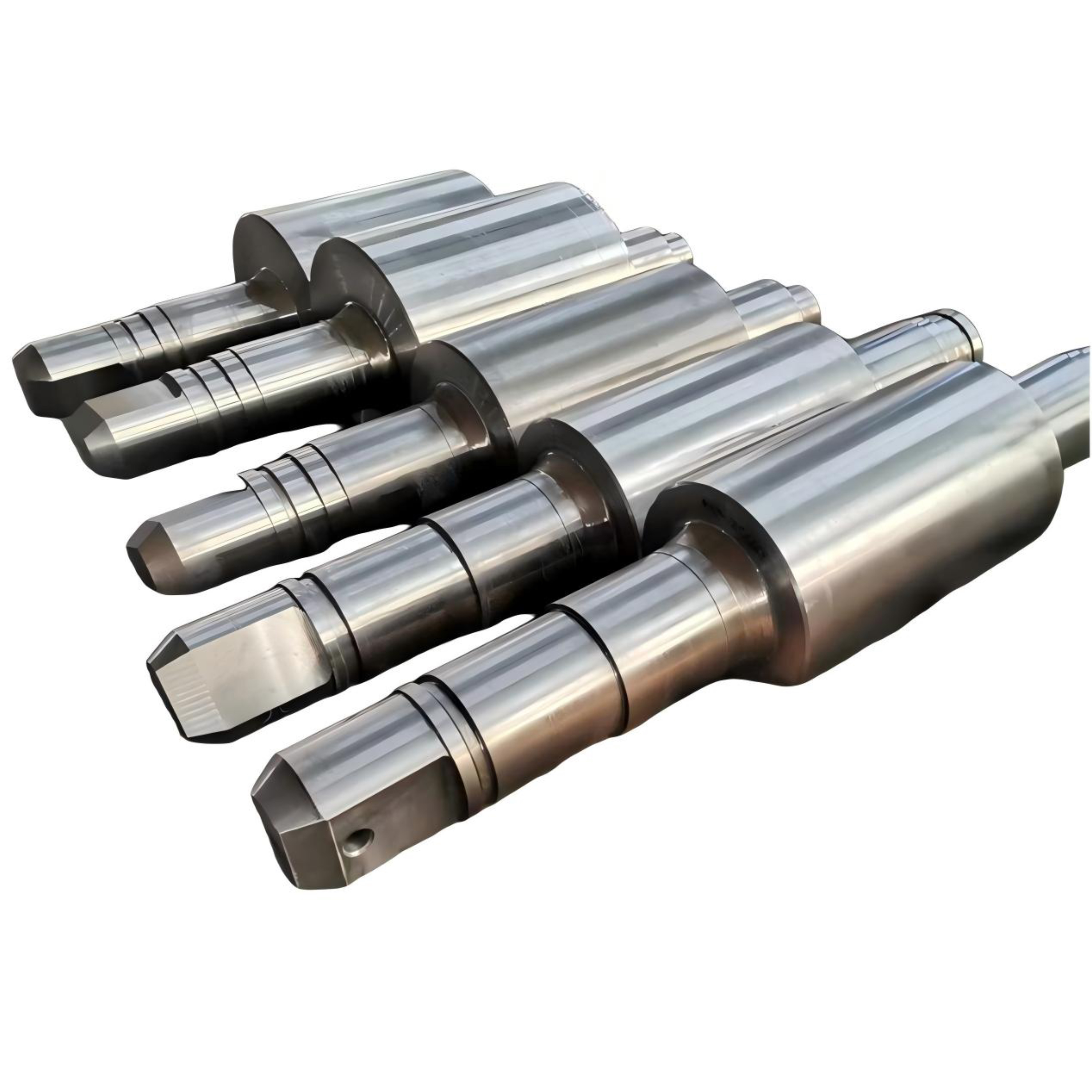
Surface hardness must remain consistent across the entire roll barrel. Acceptable variance is typically limited to ±1 Shore C. Uneven hardness leads directly to uneven wear during the rolling campaign. Soft spots on the roll face wear faster, creating localized depressions. These depressions transfer to the copper strip as thick bands, destroying gauge uniformity. The depth of the hardened layer dictates the roll's usable lifespan. A deeper hardened case allows for more regrinding cycles before the roll must be scrapped or re-hardened. Buyers specify minimum usable diameter reductions based on this hardened depth. If a roll has a starting diameter of 150mm and a hardened depth of 10mm, operators can safely grind it down to 130mm before replacing it.
Rolling wide copper coils presents severe engineering challenges. Typical coil widths range from 300mm to over 1000mm. As coil width increases, the bending forces applied to the work roll increase exponentially. This requires highly specific roll rigidity. If the roll deflects excessively, the mill cannot achieve uniform reduction across the strip width. Engineers combat this deflection by increasing the roll barrel diameter where mill housings permit, or by utilizing backup rolls in 4-high or 6-high mill configurations. The work roll itself must be forged from steel with a high modulus of elasticity to resist this mechanical bending. Operators monitor the rolling force feedback from the mill's load cells to ensure they do not exceed the roll's elastic limits.
Work rolls are rarely ground perfectly flat. They require a precise initial crown profile to compensate for two opposing forces: mechanical deflection and thermal expansion. Mechanical deflection bends the roll, creating a concave gap. The heat generated by plastic deformation of the copper heats the center of the roll faster than the edges. This causes the roll center to expand, creating a convex thermal camber. The initial ground crown perfectly balances these forces at operating speed and temperature. If the crown is too high, the strip develops center buckles. If the crown is too low, the strip develops wavy edges. Roll shop technicians use CNC grinders to apply parabolic or sinusoidal crown profiles based on the specific thermal dynamics of the mill.
Final-pass work rolls require extreme dimensional precision. Concentricity, cylindricity, and runout tolerances are often specified within a few microns. Any deviation in roundness translates directly into gauge chatter on the 9µm foil. The surface finish must be meticulously controlled. Mirror-finish capabilities are necessary to achieve Ra values below 0.05 µm. This ultra-smooth finish minimizes the surface area of the copper foil, drastically reducing surface oxygen rates. Achieving these tolerances requires state-of-the-art CNC roll grinders equipped with continuous measurement calipers and specialized polishing attachments. Operators filter the grinding coolant through diatomaceous earth systems to remove microscopic swarf that could scratch the roll surface during the final polishing passes.
Recommended Grinding Tolerances for Foil Finishing Rolls | ||
Parameter | Acceptable Tolerance Range | Impact of Out-of-Tolerance Condition |
|---|---|---|
Total Indicator Runout (TIR) | < 0.002 mm | Transverse gauge chatter, mill vibration. |
Cylindricity | < 0.003 mm | Uneven tracking, localized gauge variations. |
Surface Roughness (Ra) | 0.02 - 0.05 µm | Poor substrate adhesion, accelerated oxidation. |
Crown Accuracy | ± 0.001 mm from target profile | Strip shape defects (center buckle, edge wave). |
The intense heat treatment required to achieve 95 Shore C hardness introduces massive internal stresses within the steel forging. If left unmitigated, these residual stresses act as ticking time bombs. Operational thermal shock or normal rolling pressures cause these stresses to exceed the steel's tensile strength, resulting in explosive spalling. Proper tempering cycles are mandatory to relieve these stresses while maintaining surface hardness. Metallurgists carefully control the cooling rates during quenching and follow up with prolonged, low-temperature tempering holds to stabilize the microstructure and ensure operational safety. Roll manufacturers provide residual stress measurement reports using X-ray diffraction techniques to verify the safety of the roll before shipment.
The core of any high-performance work roll lies in its heat treatment. Advanced suppliers utilize dual-frequency induction hardening or differential temperature quenching to achieve the required microstructure. Dual-frequency induction allows precise control over the depth and intensity of the hardened case. Lower frequencies penetrate deep into the steel, while higher frequencies rapidly heat the extreme surface. This creates a smooth hardness gradient, eliminating sharp transition zones that are prone to subsurface shear failures. Evaluating a supplier's Forged Roll Quality Capabilities requires a deep dive into their thermal processing equipment and metallurgical control software. You want to see automated quenching systems that eliminate human error during the critical cooling phases.
Visual inspection is entirely insufficient for cold rolling rolls. Mandatory non-destructive testing (NDT) must be performed before any roll leaves the manufacturing facility. Ultrasonic testing (UT) probes the internal structure of the forging, detecting subsurface micro-cracks, voids, or non-metallic inclusions. These internal flaws act as stress concentrators and inevitably lead to spalling under high rolling loads. Magnetic particle inspection (MPI) detects fine surface cracks generated during the grinding or hardening processes. Buyers demand comprehensive NDT reports mapped to the specific serial number of every roll purchased. If a supplier hesitates to provide these logs, operators reject the shipment immediately.
Mandatory NDT Inspection Protocols for Work Rolls | ||
Inspection Method | Target Defect | Frequency of Testing |
|---|---|---|
Ultrasonic Testing (UT) | Subsurface voids, deep inclusions, internal forging bursts. | 100% of rolls after rough machining and after final heat treatment. |
Magnetic Particle Inspection (MPI) | Surface micro-cracks, grinding burns, heat checking. | 100% of rolls after final grinding and polishing. |
Hardness Mapping (Equotip) | Soft spots, uneven hardness gradients across the barrel. | Multiple points along the barrel and journals prior to shipment. |
A common procurement error involves specifying a roll that exceeds the capabilities of the existing cold rolling mill setup. Upgrading to a harder, more rigid roll might seem beneficial, but it shifts the weak link to other mill components. A highly crowned roll requires higher separating forces to flatten the strip, exceeding the mill's hydraulic screw-down capacity. A roll designed for higher speeds overwhelms the existing coolant system, leading to uncontrolled thermal camber. Engineering teams ensure the new roll specifications align perfectly with the mill's mechanical and thermal limits. They review the mill's original equipment manufacturer (OEM) manuals to verify maximum bearing load capacities before installing heavier forged rolls.
Forged roll manufacturing is not a rapid process. The timeline from ingot melting to final CNC grinding spans 3 to 6 months. Rushing this process, particularly the tempering cycles, guarantees premature roll failure. Mill operators account for these extended lead times in their procurement strategies. Maintaining a calculated safety stock of work rolls prevents catastrophic mill downtime. Relying on just-in-time delivery for custom-engineered forged tooling exposes the production line to severe supply chain vulnerabilities. Procurement teams establish staggered delivery schedules with their suppliers to ensure a continuous pipeline of fresh tooling arrives at the plant.
Integrating a newly ground work roll into the mill carries operational risks. Cold rolls are highly susceptible to thermal shock. Hitting a cold roll with hot copper strip and high-pressure coolant causes immediate surface cracking. Operators follow strict run-in procedures to protect the tooling.
Pre-heating: Circulate warm mill coolant over the rolls for 30 to 60 minutes before threading the copper strip.
Low-Speed Threading: Thread the mill at 10% of normal operating speed to establish initial strip tension and verify tracking.
Conservative Reductions: Limit the first pass reduction to 50% of the target draft to allow the roll to build a stable thermal camber.
Temperature Monitoring: Use infrared pyrometers to monitor the roll barrel temperature, ensuring it stabilizes before ramping up to full production speed.
Surface Inspection: Stop the mill after the first coil and visually inspect the roll face for any signs of heat checking or abnormal wear patterns.
The most reliable suppliers control the entire manufacturing process in-house. Fragmented supply chains, where forging, heat treatment, and grinding are outsourced to different vendors, introduce massive quality control risks. A premier Cold Rolling Mill Roll Supplier manages everything from ingot melting and open-die forging to induction hardening and final CNC inspection. This vertical integration ensures complete traceability. If a roll fails prematurely, an integrated supplier traces the exact heat lot, forging reduction ratio, and tempering cycle to identify the root cause and implement corrective actions. Auditors visit the supplier's facility to verify the presence of heavy forging presses and dedicated heat treatment bays.
Off-the-shelf rolls rarely perform optimally in high-precision copper foil applications. The supplier demonstrates strong technical support capabilities. They routinely analyze your specific mill data, including maximum rolling force, operating speed, coolant type, and target coil weights. Based on this data, their engineering team recommends custom crown profiles and specific surface roughness parameters. A supplier who simply asks for a dimensional drawing without understanding the process parameters operates as a basic machine shop, not a tooling partner. You need metallurgists who understand the specific tribology of rolling non-ferrous metals.
To receive an accurate proposal, procurement teams provide comprehensive technical data. A standard drawing is insufficient. A proper Custom Copper Foil Roll Inquiry includes the mill type, maximum rolling force, target foil thickness, and required Ra finish. The inquiry details current roll failure modes. If your current rolls fail due to spalling, the new supplier uses this information to adjust the heat treatment profile. Providing detailed operational context allows the supplier to engineer a roll that solves specific production bottlenecks. Include data on your coolant filtration micron rating, as this impacts the supplier's recommendations for final surface polishing.
Audit current work roll wear profiles using profilometers to identify localized wear bands or chatter patterns.
Request complete ultrasonic testing (UT) and magnetic particle inspection (MPI) logs for all incoming roll shipments.
Map out your mill's maximum separating force and coolant flow rates before drafting new tooling specifications.
Implement a slow-ramp pre-heating protocol for all new rolls to prevent thermal shock during the first reduction pass.
A: Cold rolling creates a horizontal grain structure within the copper. This aligned grain structure offers vastly superior fatigue resistance and flexibility compared to the vertical, columnar grain structure of electrodeposited copper. It prevents micro-cracking during dynamic bending in flexible circuits.
A: For finishing passes on non-ferrous metals like copper, the target surface hardness is typically 90-95 Shore C. This extreme hardness provides necessary wear resistance, but it must be paired with a softer, ductile core to absorb mill stresses and prevent breakage.
A: The 3% chromium content in Cr3 steel acts as a strong carbide former. This allows for deep, uniform hardenability during heat treatment and provides exceptional wear characteristics, maintaining the critical surface finish longer than standard carbon steels.
A: The roll's Ra value transfers to the foil's matte side, dictating its mechanical peel strength when laminated to FR4 substrates. A highly controlled, smoother finish reduces microscopic crevices, minimizing the surface area vulnerable to rapid oxidation.
A: Beyond dimensional drawings, suppliers need your mill type, maximum rolling force, target foil thickness, coil width and weight, required surface hardness, and details on your coolant system to engineer the correct crown and heat treatment profile.
A: Regrind life depends entirely on the specified depth of the hardened layer and the severity of wear or damage sustained during the rolling campaign. Once grinding penetrates past the hardened case, the roll must be re-hardened or scrapped.
A: Spalling is typically caused by a combination of subsurface non-metallic inclusions, excessive residual stress from improper tempering, and operational thermal shock. These factors create internal shear forces that exceed the steel's tensile strength, causing chunks of the surface to break away.


